Krishnaa Energy Pvt Ltd

- Products
- Electronic-Equipments
- Cable Trays
Product Range
Fact Sheet
- Location:Tamil Nadu, India
- Year of Establishment:1997
- Business Type:Manufacturer, Exporter
- Turnover:Rs. 50 Lakh - 5 Crore
(or USD 100 K - 1 Million) - Main Products:Electronic Equipments, Energy Meters
- Reviews & Rating:

Get Verified, Sell more with
- Buyer's trust
- Faster conversions
- Better Rankings
- More
Its Free
Verify NowCable Trays
Krishnaa Energy has invested in CNC machines for providing state-of-art panel products and cable trays to its customers. We are manufacturing all possibilities of a typical cable tray layout
- FOB PriceNA
- Min Order QuantityNA
- Payment TermsNA

Other Details
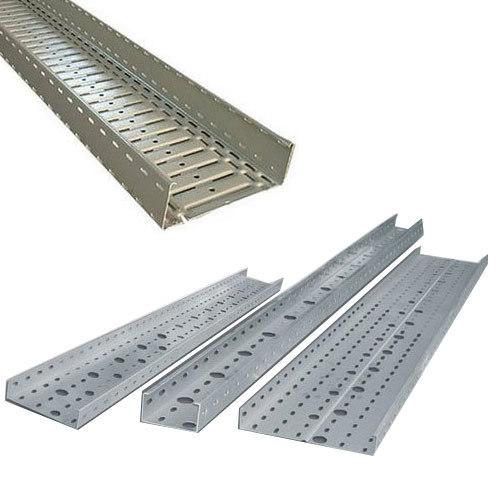
Krishnaa Energy has invested in CNC machines for providing state-of-art panel products and cable trays to its customers. We are manufacturing all possibilities of a typical cable tray layout namely,
Straight Section
Cable Tray drop
4-way junction
T-Junction
L-Junction
Reducer
We use G.P. (Galvanic Primer) sheet for manufacturing the cable trays and we undertake orders for perforated type, ladder type or box type (Un-perforated) as per the requirements of the client.
The Perforated Tray is manufactured from the pre-galvanized sheet metal and the tray is designed for a uniform load of at least 200 N per 1000 mm tray.
The trays shall be fabricated in a length of 2.4 M.
The perforated cable trays shall be manufactured from good commercial, high grade strength.
GI sheet steel having minimum thickness of 1.6 mm up to 300 mm tray and 2 mm thickness for 450 mm, 600 mm and 750 mm which can be used for indoor/out door use having moderate humidity and air pollution.
The zinc coating surface with a approximate thickness of 80 micron.
All manufacturing process including punching, cutting, bending and welding of perforated cable trays will be finished and burrs are removed before dispatch.
The joints of two trays will be butt construction and the joints will be coupled with the help of coupler plates by nuts and bolts.
The coupler plates, nuts and bolts will be properly hot dip galvanized, where the bends of the trays are required at site the same shall be supplied without any extra cost.
While adopting the modules at site if cutting of any length is required the same will be cut at site and joined by nuts and bolts with the help of coupler plates.
The perforated cable trays will be supported on the supporting arrangement made approximately at a distance of 0.1 to 1.2 m center to center either from ground/wall or ceiling.
However, the supporting system shall be designed as per site condition.
The brackets and supporting system shall be painted with two coats of zinc chromate primer followed by two coats of synthetic enamel paint.
The perforated trays are free from sharp edges and burns.
The perforated trays will be installed in such a way that as far as possible the Cables can be laid directly in place rather than be pulled through. The cables shall be fixed in the perforated trays by means of plastic ties or plastic coated wires etc.
Images