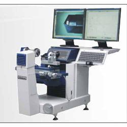
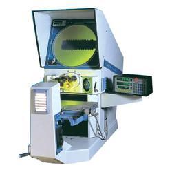
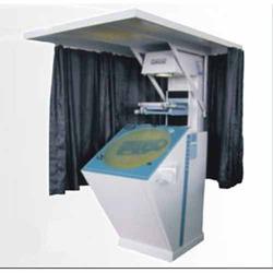
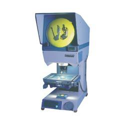
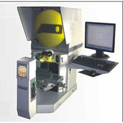
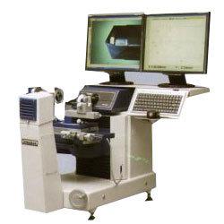
Cutting Tool Inspection Systems
| Light Path | Horizontal |
| Imaging System | High resolution CCD Camera coupled to a 7:1 Zoom Lens |
| Magnification | 20x to 140x, in 5 steps. Magnifications can be decreased to 10x or increased up to 280x by use of Auxiliary Lenses. Optional Motorised 80 mm Lens available. |
| Workstage Table Top Area | 450x160 mm, with dove-tail slot |
| Measuring Range X, Y Axis | 300x150 mm, with quick release in X axis |
| Resolution / Measuring System | 0.001mm, built in Glass Scales |
| Profile Light | 9 segment LED light source with swivelling lamp-house to accomodate long jobs |
| Surface Light | 64 segment programmable, rotating ring light enables correct lighting conditions for all applications. |
| Auxiliary Lighting | An optional auxiliary light is provided through a flexible tube, or through the lens for difficult lighting conditions |
| Display | Two 19 inch LCD flat screen monitors, one for the image, the other for tracing of parts to CAD and display of measured results / reports |
| Geometric Measurement Software | Powerful microprocessor based controller with advanced Geometric Measurement Software DGMS-3, covering all measuring applications. |
| Inspection Tools | Scanning of irregular features, Mouse Point, Edge Tools like Circle, Arc, Point Length, Tangential, Peak Point, Thread Profile and Cross Hair for use like a Profile Projector. Cross Hair rotates for angle measurement on screen. |
| Programming Function | All measurements get stored automatically as a program and can be recalled later for repeat measurement |
| Geometric Tolerancing | Geometric Tolerancing of length, diameter, angle, concentricity, parallelity can be user defined to provide Pass / Fail reports. |
| Drawings, Import / Export | Drawings of the part can be generated and transferred to CAD as a DXF file for comparison with the master design drawings. Graphical print out of drawings with dimensions can be generated. Form error of parts can also be measured. |
| Reports | Pass / Fail Reports with tolerances can be created, stored or exported to a spreadsheet |
| Spc Data | The DGMS 3 Software allows for the collection of data for SPC and is displayed in the form of bar-charts and graphs. 1, 2, & 3 sigma tolerance-bands in colour provide data for process control. Cp and Cpk values are also displayed. |
| Power Supply | 230V, 50Hz, AC, Single Phase |
Manufacturer and supplier of application software packages such as computer software packages, computer application software packages, graphics software packages, data software packages and desktop software packages.
More details:View company website
Its Free
Verify Now
